


Simulating a fan
$43 $50
In this project, a motor jet fan is simulated in a circular channel using the frame motion feature in Fluent. You can access CAD and mesh files and simulated files by purchasing this product. With the purchase of this product, a training video will be sent to you about the Fluent simulation steps and a full explanation of the options.
Add to cart
Share this Post
In this project, a motor jet fan is simulated in a circular channel using the frame motion feature in Fluent. A mechanical fan is a machine used to generate flow inside a fluid. This is achieved by rotating several blades connected to a hub and shaft driven by an engine or turbine. The flow rate of fans ranges from 6 to 60,000 cubic meters per minute. The blower is another name for fans in which the flow resistance is high on the downstream side of the fan.
A fan consists of a rotating set of blades or vanes that move through the air. The rotating assembly of blades and hub is known as the impeller, propeller, rotor, or runner. Usually, the fan components are placed inside some housing that may direct the airflow in a way that prevents objects or fan blades from hitting and increases safety. An electric motor drives most fans. But other power sources such as hydraulic motors and internal combustion engines may also be used.
Fans produce airflow with high volume and low pressure (although higher than ambient pressure) and are the opposite of compressors that have increased production in relatively low volume. A fan blade often rotates when exposed to an air current, and devices that use this feature, such as anemometers and wind turbines, often have a fan-like design.
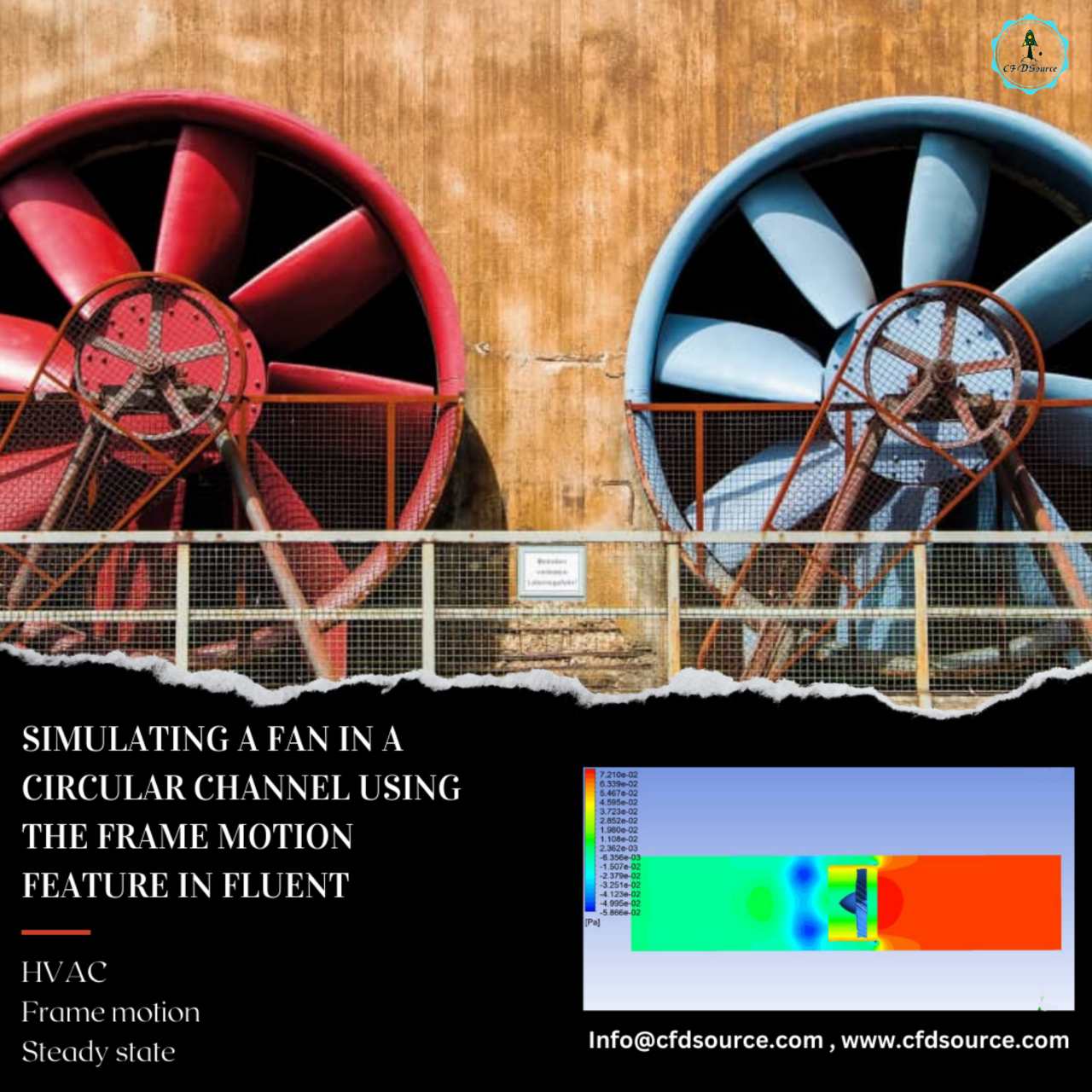
In this project, a jet engine fan in a circular channel has been simulated using the frame motion feature in Fluent. Using the Frame motion feature, we can steady-state simulate rotating equipment. This work is economical. Saving computing costs and runtime helps us a lot. In this problem, the fan’s rotational speed is 30 rpm, and the air inlet velocity to the channel is 0.1 m/s. 
This simulation aims to check the frame motion capability in Fluent. By analyzing the simulation results, we can evaluate the accuracy of this option in Fluent.
Method:
The velocity inlet boundary condition is defined with a value of 0.1 m/s, and the pressure outlet boundary condition is defined with zero pascal gauge pressure. In this project, we have two cell zones that are separated from each other by the interface boundary. For the cell zone of the fan, frame motion has been used with a rotational speed of 30 rpm. The geometry of this project is designed by space claim software. The meshing of this geometry is done by Ansys meshing software, and the number of elements used for this project is 373443.
Result:
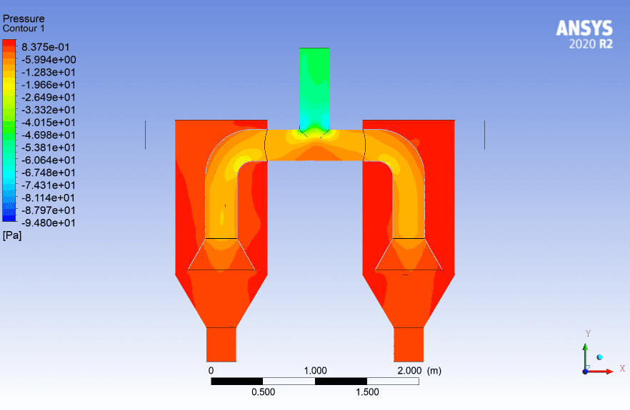
After the simulation, we can observe the speed and pressure contours. We can see that the static pressure behind the fan is higher than in front of the fan, and the speed in front of the fan is higher than behind it. Since fans are used to creating flow, they do this by creating velocity in the flow, which is associated with reducing static pressure. On the other hand, we can see that the zone for which we have defined the rotational velocity by frame motion has increased linearly along the radius of the rate inside, and there is a speed discontinuity at the interface boundary. This is because a radial momentum source term is included in the fan for the cell zone, but there is no source term outside that zone. This incident can be seen as one of the disadvantages of using the frame motion feature. We must perform transient simulations and use mesh motion to achieve a more accurate simulation.